This project was made in 2013, I was around 19. My methods and material where quite primitive at that time…
How it works
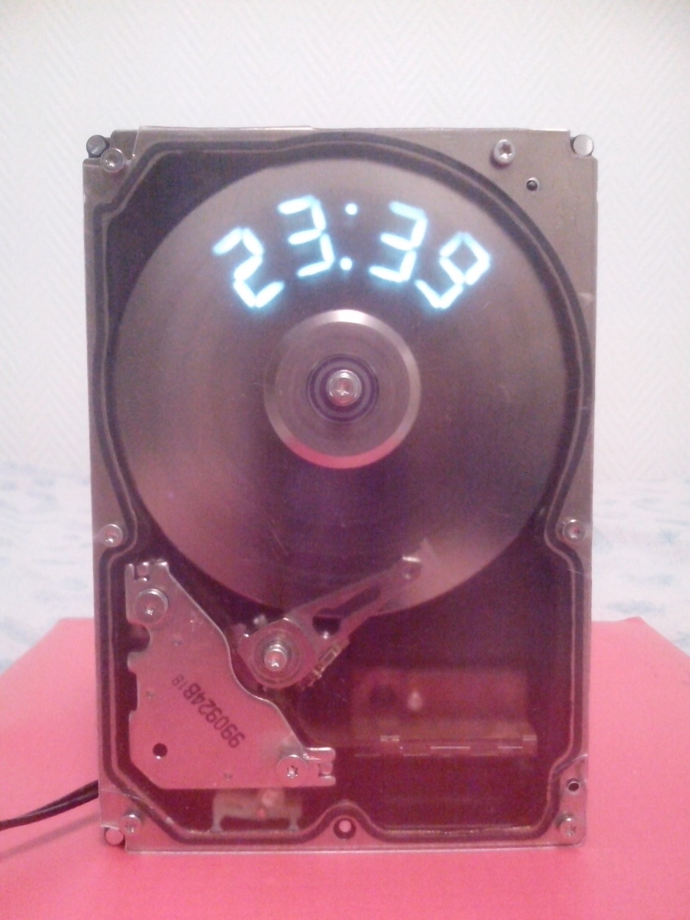
The spinning disk of the drive is cut with number shape from 0 to 9 and one separator. To avoid vibration and noise, an extra hole is present to preserve the matching between the gravity center and the rotation point. Behind the disk, we find 5 groups of LEDs (4 for the digit numbers of the time and one for the separator), when the correct number of the disk passes in front the LED flash to display that number. Because of the high RPM of the disk and the persistence of our retina we see a persistent display of the time.
This project was mainly built using my CNC milling machine.
Parts description
Disk
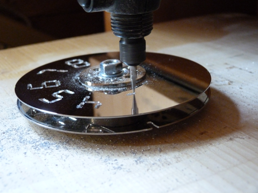
Milled disk
The disk has been milled by my homemade CNC with an engraving cutter. The milling was quite long and difficult due to the very hard material of the disk.The design and the balancing were made on Solidworks.
Milling
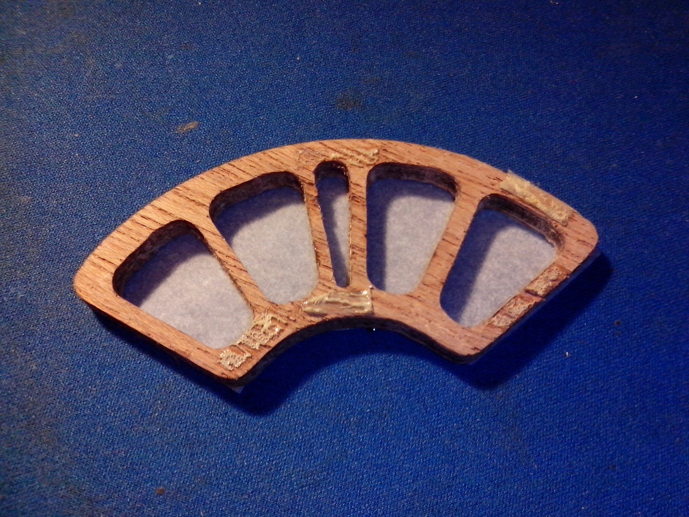
Compartments
The compartments are made to isolate the light from the LED to ensure clear display of the number. It is also manufactured in wood by the CNC machine. The result was quite satisfying. Some baking paper is pasted to get a nice uniform diffused light.
Electronics
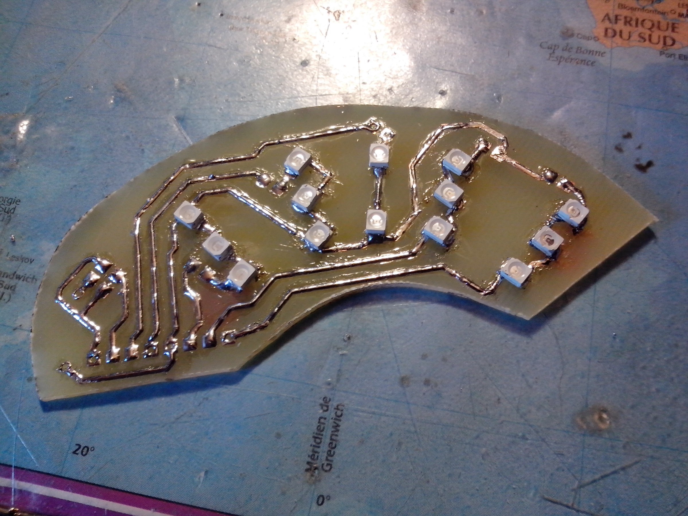
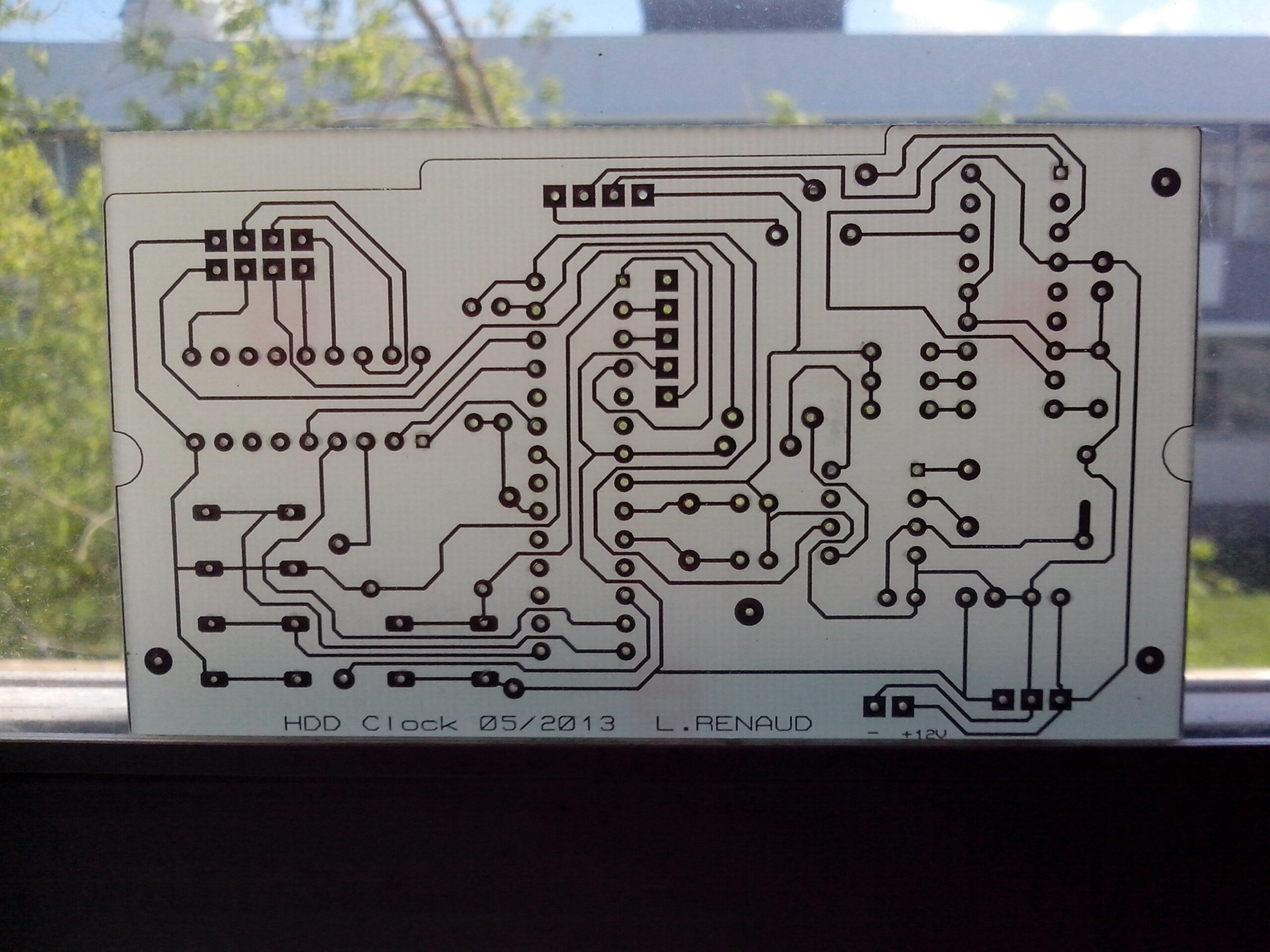
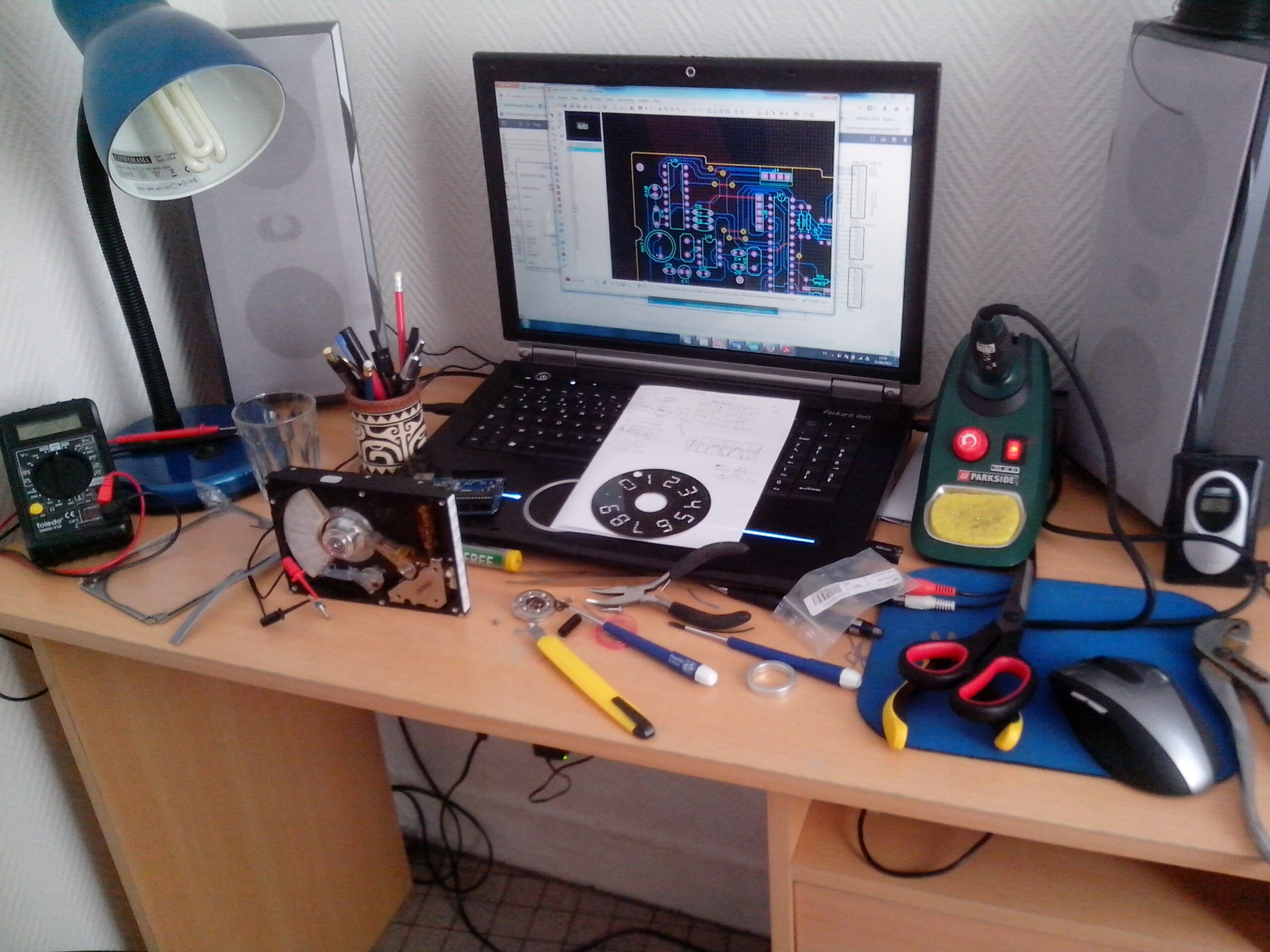
All the schematics and PCB layout are designed on Proteus.
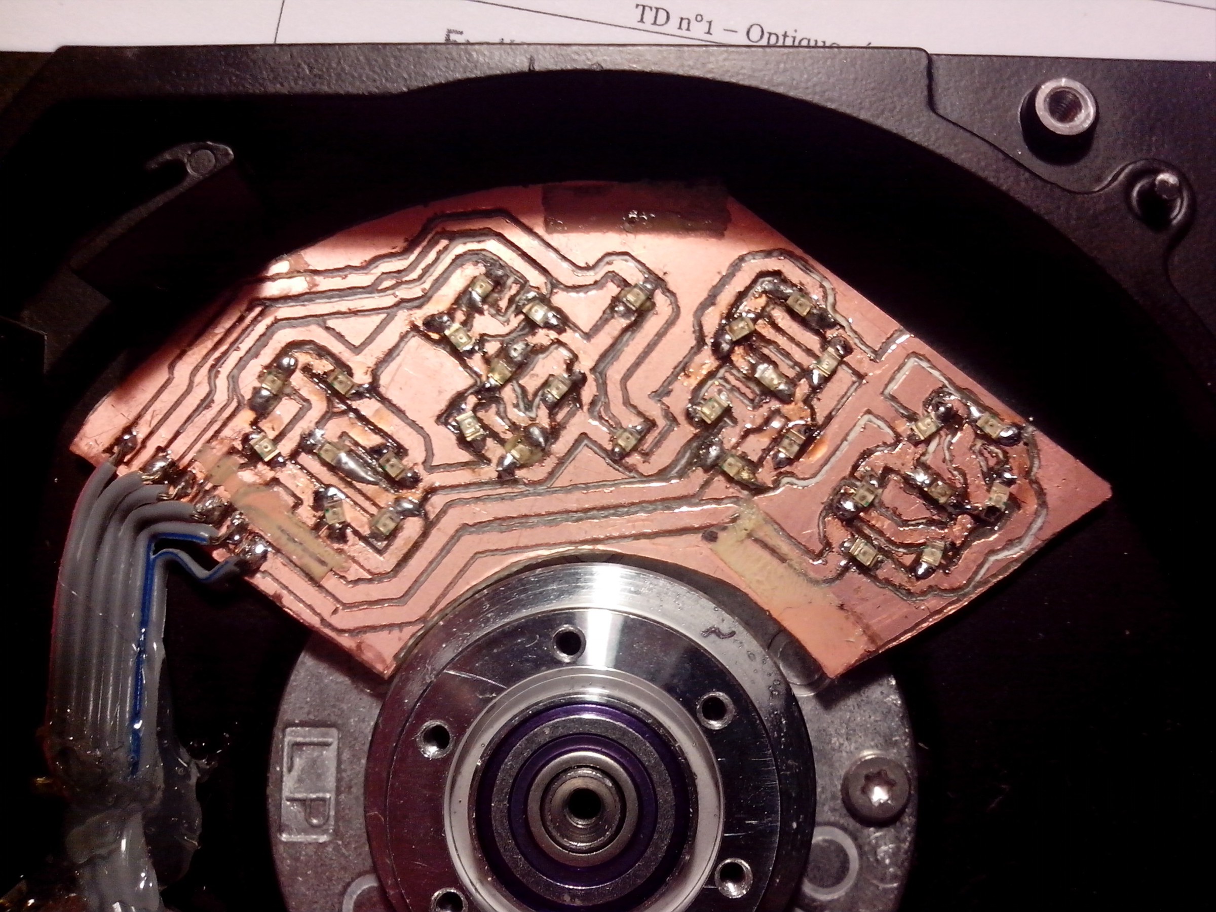
The SMD LEDs behind the disk are soldered on a PCB and are isolated in compartments. The first PCB version was milled using the CNC, then I was able to use the chemical etching process of my university to get a better result.
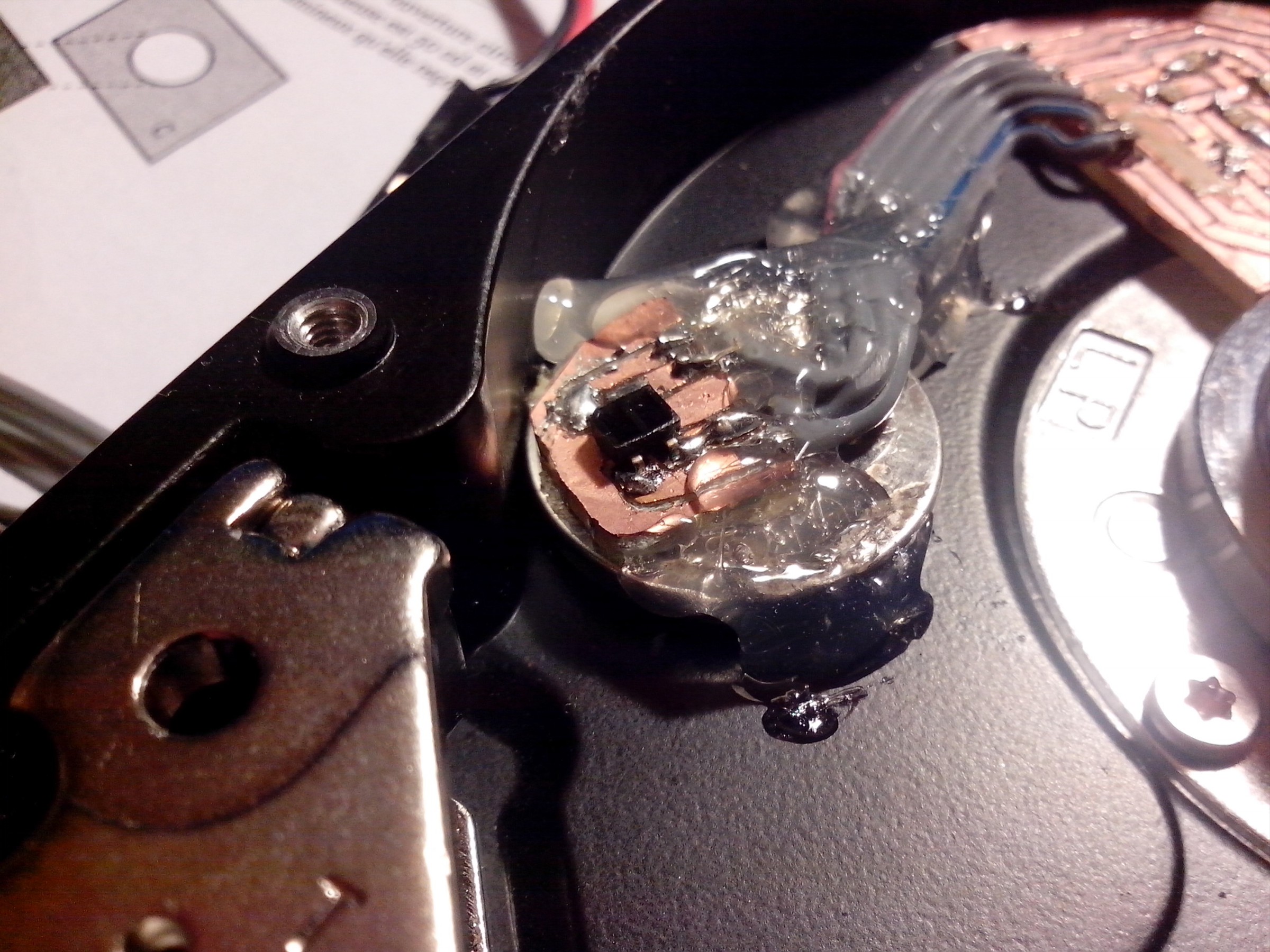
There is also an optical switch to measure the RPM of the disk and adjust LED flash frequencies.
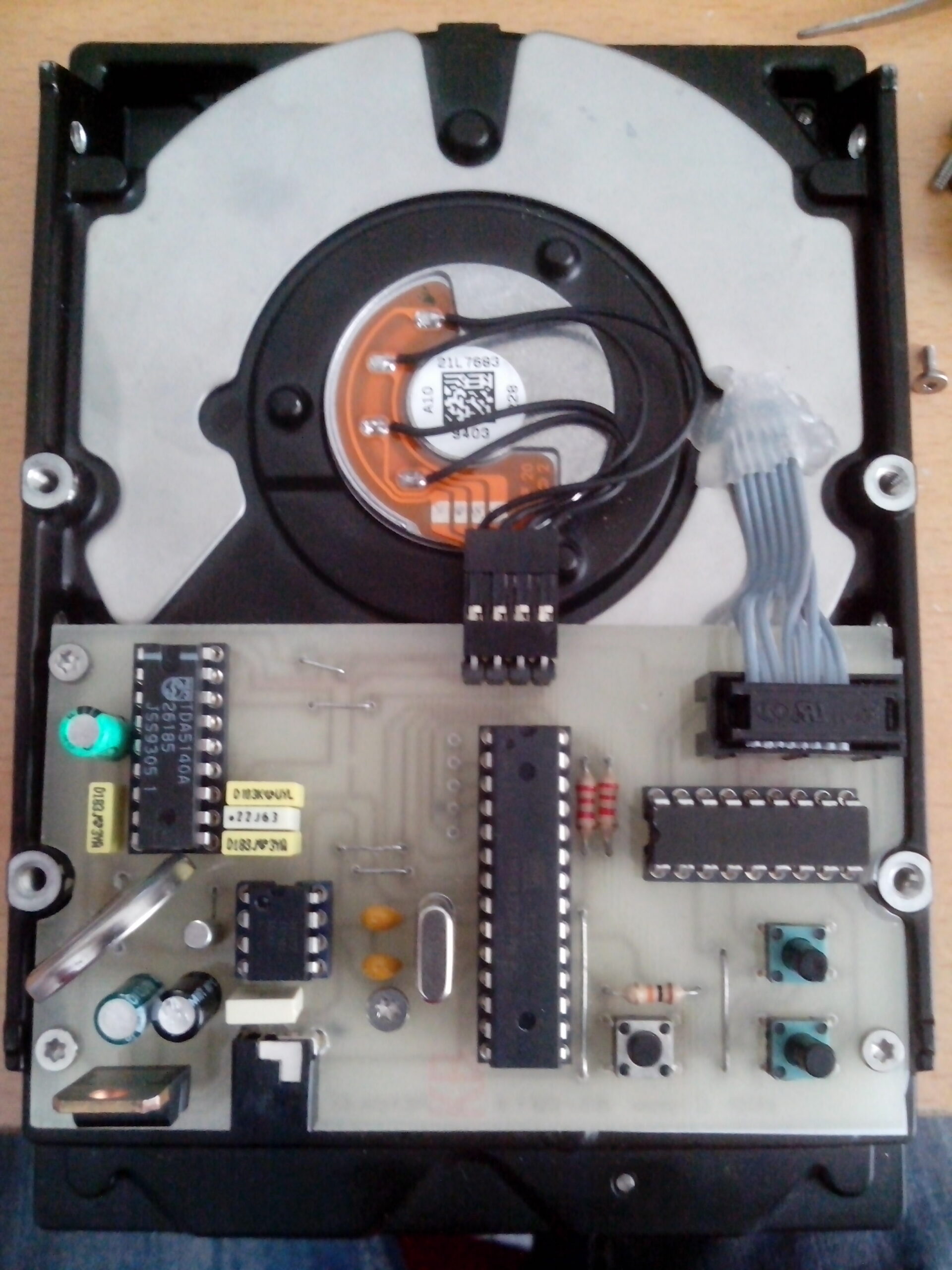
Main board
An Atmega328 microcontroller is used to command the LEDs
The power supply for the uC and the motor is 5V and achieved by using a LDO (7805)
The LED are driven by NPN transistors array (ULN2803)
The RPM sensor is an optical switch
The time is provided by an I2C RTC (DS1907) a coin cell battery insure the time is not reset when the power supply is disconnected.
3 push buttons are used (2 for increment or decrement the time and the other one to reset the uC)
The brushless driver used to drive the motor is a TDA5140A
The main board was first made with jumpers wore and an arduino then I design a PCB and printed it at ENAC the place where I made an internship.


VecNa
the case ‘website’ is useless…
good project !
i will try do one, do u have a git ? with the code ? to help me pls
thanks bro !
keep the good work !
lulu
Hi man,
Yeah no problem I will post the git soon.
Thank you